Custom IGBT Heat Sink Solutions Built for Production
Custom IGBT heat sinks and liquid-cooled assemblies engineered to move cleanly from prototype to volume production. Convert thermal targets and CAD into a reliable, manufacturable cooling solution with coordinated thermal engineering, DFM review, and production planning.
200,000
Aluminum heat sinks per month
10+ bar
Liquid plate operation, structure dependent
±0.002–0.008 mm
CNC machine capability
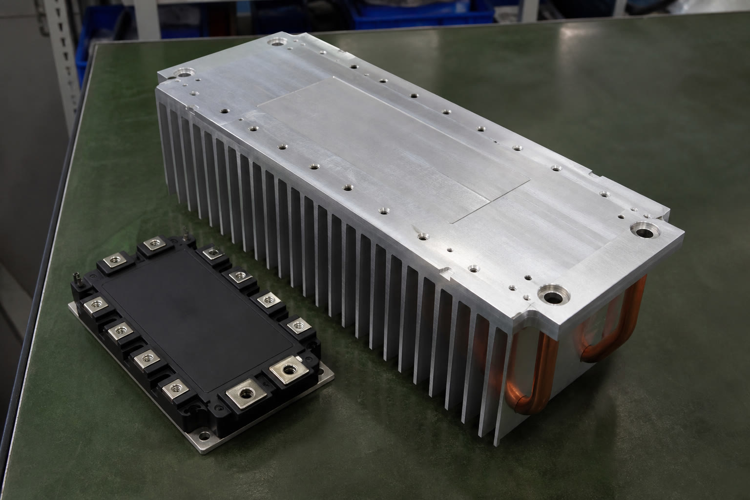
Engineering-led manufacturing
One coordinated supply chain for skiving, extrusion, cold forging, heat pipes, brazing, soldering, FSW, CNC, and testing.
Built around your application
What you get with an IGBT cooling partner
The cooling structure is matched to your load, airflow, footprint, mounting conditions, and cost target, while the manufacturing route is planned for repeatable production.
01
Thermal performance
Designs are matched to heat load, airflow, and footprint to meet junction temperature limits without unnecessary material or fan cost.
02
Controlled pressure drop
Fin geometries and base structures are selected around pressure drop, mechanical constraints, fan power, and system noise.
03
Production-ready prototypes
Prototype parts use the intended production process wherever possible, reducing re-qualification risk between design validation and volume manufacturing.
04
Early DFM review
Mounting holes, flatness strategy, machining allowances, plating impacts, and assembly requirements are reviewed before production tooling or release.
05
Integrated processes
Skiving, extrusion, cold forging, heat pipes, brazing, soldering, FSW, and CNC are coordinated through a single supply chain.
06
Measured validation
Validation can include thermal resistance, airflow and pressure, leak and pressure testing for liquid plates, and dimensional or CMM inspection.
Cooling architecture
Select the right IGBT heat sink or cold plate
The recommended route depends on heat flux, airflow mode, module footprint, enclosure, pressure drop, and target cost.
Discuss your thermal targetSkived fin heat sinks
Aluminum or copper fins formed from the base for high density, large surface area, and low thermal interface resistance in forced-air cabinets.
Extruded aluminum heat sinks
Cost-effective for repeat production with moderate-to-high aspect ratios, plus in-house CNC machining, drilling, tapping, anodizing, and FSW assembly.
Cold forged pin-fin heat sinks
Aluminum or copper integrated pin-to-base structures with no fin draft angle, supporting multi-directional airflow in compact cabinets and fan trays.
Heat pipe-assisted assemblies
Copper heat pipes spread concentrated module heat into stamped or zipper fin arrays and machined bases. Soldering, brazing, nickel plating, and validation are available.
Liquid-cooled IGBT cold plates
Vacuum brazed, FSW, or embedded-tube plates with custom flow channels and microchannels to balance pressure drop and thermal resistance. Aluminum structures can be designed for operation above 10 bar depending on construction, with pressure and leakage testing.
Engineering support
Thermal and mechanical decisions before manufacturing
A reliable IGBT heat sink balances heat source size, airflow, fin geometry, pressure drop, mounting method, environment, and cost. Engineering support is available from an early application brief through production release.
- ✓Evaluate the thermal target and allowable temperature rise.
- ✓Select base material and fin geometry for heat spreading and convection.
- ✓Plan mounting and flatness strategies for reliable IGBT contact pressure.
- ✓Review machining, plating, assembly, and DFM requirements.
- ✓Prototype with the intended production process and validate performance.
Start with your available data
AutoCAD, SolidWorks, and Creo files are accepted. The review can begin with a finished drawing or basic application data.
Finished design
Send 2D drawings and 3D CAD for manufacturability and quotation review.
Early platform concept
Share heat load, airflow or coolant data, envelope limits, and target temperature rise.
Custom module layout
Design around exact hole patterns, creepage distances, isolation needs, and contact areas.
Prototype to production
Compress the design loop without changing the process later
Production-intent prototypes help validate thermal and mechanical performance before pilot build, reducing redesign risk and supporting PPAP or equivalent approvals.
01 · Prototype
Test real geometries
Skived and extruded prototypes accelerate airflow and pressure testing on the intended fin structures.
02 · Validate
De-risk sealing and fit
Early leakage and pressure tests on liquid plates help confirm sealing strategies and mechanical interfaces.
03 · Pilot
Synchronize the build
In-house CNC and finishing reduce handoffs while prototype, validation, and pilot runs are staged around system testing.
Application coverage
Cooling for demanding power systems
Support is available for standard IGBT module footprints as well as custom baseplates and dual-module layouts.
Technical reference
Capability and parameter guide
Use these ranges to map your requirements to a manufacturing route. Final capability is confirmed against the drawing and thermal targets.
| Parameter | Capability / range | Notes |
|---|---|---|
| Materials | AL1060, AL6061, AL6063; Cu1100 | Select for cost, weight, and thermal conductivity |
| Processes | Skiving, extrusion, cold forging, CNC, FSW, soldering, brazing, bonded fin | Chosen to match fin density, size, and volume |
| Base thickness | 1–40 mm | Skived and machined bases; thicker bases for heat spreading |
| Skived fin height | Up to 150 mm aluminum; 60 mm copper | High surface area for forced-air designs |
| Skived fin thickness | 0.2–3.0 mm typical; down to 0.05 mm available | Set by airflow and fouling risk |
| Skived fin gap | 0.2–10 mm | Set for target pressure drop |
| Extruded aspect ratio | Typically >20:1; FSW assemblies >40:1 | FSW enables ultra-wide profiles |
| FSW assembly width | Up to approximately 762 mm | Design dependent |
| Length | Skived product up to 2,000 mm; processing up to 3,500 mm | Consult for long or heavy parts |
| Cold forged pin-fin aspect ratio | Up to 35:1 | Round, oval, and straight pins available |
| Heat pipes | Typical Ø8 mm; quantity and layout customizable | For heat spreading under fin arrays |
| Surface finishes | Anodizing, hard anodizing, nickel plating, passivation, sandblasting, polishing | Consider emissivity, corrosion, and contact resistance |
| Mounting | Drilled/tapped holes, slots, isolation standoffs | Designed for module and creepage requirements |
| Testing | Thermal resistance, airflow/pressure, leak/pressure, dimensional/CMM | Test plan aligned to validation requirements |
Quality assurance
Testing you can rely on
- Thermal resistance testing: Verify design targets under specified airflow or coolant conditions.
- Leakage and pressure testing: Confirm liquid plate integrity and sealing performance.
- CMM and 2D measurement: Inspect critical dimensions, interfaces, and flatness.
- Cleanliness and surface inspection: Align inspection with drawing and process requirements.
Production footprint
Capacity for prototypes and volume
50 sets
CNC machining centers
5 sets
Skiving machines
2 sets
FSW machines
300,000
Precision machined parts/month
Liquid plate production includes vacuum brazing and embedded-tube options. Assembly lines support thermal modules.
RFQ preparation
Send the information needed for an accurate quote
Include the details below to receive a manufacturable concept, lead time, pricing, and a build plan aligned to your schedule.
Send your RFQ packageBuild with confidence
Let’s build your IGBT heat sink
Whether you need a skived aluminum heat sink, a copper-spread heat pipe module, or a vacuum-brazed cold plate, get a cooling solution that is manufacturable, repeatable, and ready for production.
Send your CAD and thermal requirements for an application review, manufacturing route recommendation, quotation, and build plan aligned to your schedule.
Request an engineering review
Share your drawing, heat load, airflow or coolant conditions, and target build dates.